By Size
Hydropower installations can be classified by size of power output,
although the power output is only an approximate diversion between
different classes. There is no international consensus for setting the
size threshold between small and large hydropower.
For the United Nations Industrial Development Organization
(UNIDO) and the European Small Hydropower Association (ESHA) and the
International Association for Small Hydro a capacity of up to
10 MW
total is becoming the generally accepted norm for small hydropower
plants (SHP). In China, it can refer to capacities of up to 25 MW, in
India up to 15 MW and in Sweden small means up to 1.5 MW, in Canada
'small' can refer to upper limit capacities of between 20 and 25 MW, and
in the United States 'small' can mean 30 MW.
The German Federal Ministry for Environment, Nature Conservation
and Nuclear Safety mentioned that a SHP is < 1 MW, everything above
is a large hydro electric plant and usually comes along with a large
dam. The International Commission on Large Dams (ICOLD) defines a large
dam as a dam with a height of 15 m or more from the foundation. If dams
are between 5-15 m high and have a reservoir volume of more than 3
million m
3, they are also classified as large dams. Using this definition, there are over 45 000 large dams around the world.
Small hydro can be further subdivided into mini, micro and pico:
|
|
< 1 MW
|
grid connected
|
special know how required
|
|
|
< 100 kW
|
partially grid con.
|
professional know how required
|
|
|
< 10 kW
|
island grids
|
small series units produced locally; professional equipment available
|
|
|
< ~1 kW
|
single households/clusters
|
often locally handmade solutions; professional equipment available
|
There is no binding definition how Mini hydropower output is to
be classified. Rules for communication avoiding misunderstandings:
Generally the terms can be used "downwards compatible". Pico- is also
Mini- but not visa versa. Specific terms (Pico, Family) should be used
only if they are required to indicate specifics. The spectrum needs
higher diversification as smaller it becomes as there are certain
differences in technique, usage, applicability and the grade of of
ability to replicate them.
Comments:
- all installations require "special" knowhow
- there are "over the counter" pico turbines available for "self installation"
- Micro hydro is perhaps the most mature of the modern
small-scale energy supply technologies used in developing countries.
There are thought to be tens of thousands of plant in the “micro” range
operating successfully in China[1], Nepal, Sri Lanka, Pakistan, Vietnam and Peru.
- Historically the term hydropower developed from naming very
small units towards nowadays huge dams. Then there where new terms
created to separate different clusters. All of them are hydropower. What
is considered "mini or "micro" may be defined once and forever ... or
not. If there are different opinions on this topic you're welcome to
open a discussion group on this.
Classification according to size has led to concepts such as ‘small
hydro’ and ‘large hydro’, based on installed capacity measured in MW as
the defining criterion. Defining hydropower by size is somewhat
arbitrary, as there are no clear relationships between installed
capacity and general properties of hydropower or its impacts. Hydropower
comes in manifold project types (see Classification
By Facility Type)
and is a highly site-specific technology, where each project is a
tailor-made outcome for a particular location within a given river basin
to meet specific needs for energy and water management services.
Large hydropower developments involve large dams and huge
water storage reservoirs. They are typically grid connected supplying
large grids. Preference for large hydro is on the decline due to the
high investment costs, long payback periods and huge environmental
impacts (losses of arable land, forced migration, diseases and damage to
biodiversity). Many
social and environmental impacts are related to the impoundment and existence of a reservoir, and therefore are greater for 'large hydro' plants with reservoir.
Small hydropower stations are typically run-of-the-river.
They combine the advantages of hydropower with those of decentralised
power generation, without the disadvantages of large scale
installations.
Advantages
include: low distribution costs, no/low environmental costs as with
large hydro, low maintenance and local implementation and management.
Power generated with small hydro station can be used for
agro-processing, local lighting, water pumps and small businesses
[1].
The constructions and integration into local environments of
Small Hydro Power (SHP) schemes typically takes less time and effort
compared to large hydropower plants. For this reason, the deployment of
SHPs is increasing in many parts of the world, especially in remote
areas where other energy sources are not viable or are not economically
attractive.
However, larger facilities will tend to have lower costs on a
USD/kW basis due to economies of scale, even if that tendency will only
hold on average. Moreover, one large-scale hydropower project of 2,000
MW located in a remote area of one river basin might have fewer negative
impacts than the cumulative impacts of four hundred 5 MW hydropower
projects in many river basins (see also
Negative Environmental Impacts).
For that reason, even the cumulative relative environmental and social
impacts of large versus small hydropower development remain unclear, and
context dependent.
General concepts like ‘small’ or ‘large hydro’
are not technically or scientifically rigorous indicators of impacts,
economics or characteristics. Hydropower projects cover a continuum in
scale, and it may be more useful to evaluate a hydropower project on its
sustainability or economic performance, thus setting out more realistic
indicators[2].
By Facility Type
Hydropower plants can be classified in three categories according to
operation and type of flow (see figure a-c). a) Run-of-river (RoR),
b) storage (reservoir) and
c) pumped storage HPPs
In addition, there is a fourth category (d) called in-stream technology, which is a young and less-developed technology.
Storage HPPs require high dams and big storage areas to be
flooded. Such is usually the case in big infrastructure projects
including the known environmental impacts. Small and micro hydropower
usually avoids those but utilizes water that runs of a river.
Pumped storage HPPs work as energy buffer and do not produce net energy.
a) Run-of-River Hydropower Plant
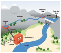
Run-of-River Hydropower Plant
|
- RoR plant mainly produce energy from the available flow of the river, taking advantage of the natural elevation drop of a river
- It is suitable for streams or rivers that have a minimum flow
all year round or those that are regulated by a larger dam and reservoir
upstream
- Water is diverted into a penstock and channeled to the turbine and then returned to the river
- RoR plants have either no storage or short-term storage, allowing for some adaptations to the demand profile
- Such reservoirs are usually smaller than those of reservoir
hydro power plants but nevertheless dams can be ten to twenty meters
high and can have gates to allow for water storage
- Power generation is dictated by local river flow conditions and
thus depends on precipitation and runoff and may have substantial
daily, monthly or seasonal variations
- Environmental impacts are generally lower than for similar-sized storage hydropower plants
|
b) Hydropower Plant with Reservoir
Hydropower Plant with reservoir
|
- Hydropower projects with a reservoir (storage hydropower) store water behind a dam for times when river flow is low
- Therefore power generation is more stable and less variable than for RoR plants
- The generating stations are located at the dam toe or further
downstream, connected to the reservoir through tunnels or pipelines
- Type and design of reservoirs are decided by the landscape and
in many parts of the world are inundated river valleys where the
reservoir is an artificial lake
- In geographies with mountain plateaus, high-altitude lakes make up another kind of reservoir
- Reservoir hydropower plants can have major environmental and social impacts due to the flooding of land for the reservoi
|
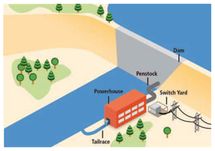
c) Pump Storage Hydropower Plant
|
|
- Pumped storage plants are not energy sources, instead they are storage devices
- Water is pumped from a lower reservoir into an upper reservoir,
usually during off-peak hours, while flow is reversed to generate
electricity during the daily peak load period or at other times of need
- Although the losses of the pumping process make such a plant a
net energy consumer, the plant provides large-scale energy storage
system benefits
- Pumped storage is the largest capacity form of grid energy storage now readily available worldwide
|
d) In-stream Hydropower Scheme
| Space for a figure
|
- To optimize existing facilities like weirs, barrages, canals or falls, small turbines or hydrokinetic turbines can be installed
- Usually the turbine is mounted on the river bottom, an existing river structure or on a floating structure
- These low-impact turbines act much like an underwater turbine and use the river current for power generation
- Basically they function like a RoR scheme
- The technologies may operate in unidirectional or
bi-directional (tidal) river flows and do not divert river flow or use
dams to retain water or create an artificial head
- As a new technology, in-stream HP is still relatively expensive
as compared to other renewable alternatives and requires further study
concerning potential environmental impacts and maintenance concerns
|
Text and Figures of this article are mainly taken from the
Chapter 5 of the IPCC Special Report on Renewable Energy Sources and
Climate Change Mitigation (2011). Prepared by Working Group III of the
Intergovernmental Panel on Climate Change [O. Edenhofer, R.
Pichs-Madruga, Y. Sokona, K. Seyboth, P. Matschoss, S. Kadner, T.
Zwickel, P. Eickemeier, G. Hansen, S. Schlömer, C. von Stechow (eds)].
Cambridge University Press, Cambridge, United Kingdom and New York, NY,
USA, 1075 pp.


